|
How to Decide the Density Range for a Design (Laser Process)
|
|---|
|
Besides brightness and uinformity need to match the requirement, for a light guide plate (LGP), there is still a key point: if there is pattern grain on it. Using laser process as an example, the factors of pattern grain is the framed components of LGP and the spacing of engraved lines. The framed components of LGP mean how many diffusion sheets will be installed and if the prism sheet is added inside. As to the spacing of engraved lines, if the spacing is too wide, the scattering capability of diffusion sheet and prism sheet will be not able to cover the pattern. Therefore, you must confirm the maximum spacing between engraved lines before you make a LGP by laser process.
|
|
How to find the spacing limitation between engraved lines?
|
|
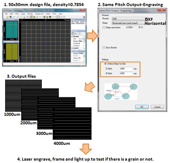
1. Create a 50x50mm design file with single density =0.7854: a continuous line in output result
|
|
2. Use Same Pitch Output-Engraving : Select DXF format, Horizontal Line, and key in different X/H pitch conditions to output (1000/2000/3000/4000um)
|
|
3. Engrave these outputs (with different pitch) on one PMMA, and frame with light source, reflection sheet, diffusion sheet, prism sheet...
|
|
4. Light up to confirm if there are pattern grain on each condition
|
 |
|
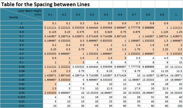
From the test as above, you can make sure the limitation of the line spacing. And then, you can fine the suitable density range for LGP design based on the density-spacing table.
|
|
For example of Line output, after testing, the maximum spacing limiation is 3mm/3000um, and you want to use laser engraved continuous line to maufacture a LGP (Line output). For laser line output, you still need to measure the width of the engraved line (Laser Beam Height). If Laser Beam Height is 200um, check the spacing table (the number in the table is the spacing (mm) under specific Laser Beam Height and density), and you can find 0.07~1 can be used to design without pattern grain. With regard to brightness and uniformity, you need to adjust further based on the test data.
|
 |
|
If you plan to engrave dash line, please refer Same Size Output and Same Pitch Output related table.
|
For Same Size Output, you can select Same Size Output-Engraving and choice the DXF format. After deciding the shape width, and you can find your suitable density range based on the density-spacing table. For example, you would like to engrave 2mm horizontal lines for your LGP, and also the spacing limitation is 3mm. Based on the table, on the horizontal direction (Table I), when the density is 0.1 and 0.2, the spacing will be 3605um and 1963um reapectively. On the vertical direction, when density is 0.4, the spacing is 2802um (Table II). Summary that density from 0.4~0.7854 is your suitable design range.
|
For Same Pitch Output, select Same Pitch Output-Engraving and choice DXF format. Generally, the setting of pitch determines the spacing between lines. So if your limitation is 3mm, just set up the pitch <3000um.
|
|
Density-Spacing Table: Download
|
|
|
|
|