index(feedback 123)
Backlight Design of Feedback ABC
email: support@febees.com
Abstract
Mesh design is issued with the BacklightFly promotion, currently the mainstream of the industry, the first article mentioned the concept of density design, this paper provides the basic concepts of correction method.
Preface
When we design is complete, a draft proofing lighting, the general we will get a set of brightness values like Figure 1 to determine the product specifications of the uniformity and brightness
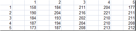 |
Fig 1 |
There is often a gray scale CCD photos like Figure 2 to determine the taste is good, the reader how to use BacklightFly to modify the next design. Through our software you will find is that their original nature.
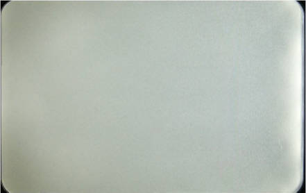 |
Fig 2 |
Simple hypothesis
We assume that the optical high places need to reduce the density, whereas increased density, in order to simplify the design not to consider the complex into the light direction. Therefore, we under a light to modify the density, as density ABC mentioned L ~ ID (a light ~ into the light intensity X density), the most direct way is:
D1/D0=Target/L0 ----(1)
D1=D0*Target/L0 ----(2)
Target = Refers to the target value or average
L0=The amount of light (measured value)
D1=Density of the new design
D0=Density of the original design
In the absence of incident light changes and other factors considered, we propose to amend the magnitude less than the calculated value, so we revised the formula for the correction
(D1-D0)/D0=(Target-L0)/L0 ----(3)
D1=D0*(1+Factor*((Target-L0)/L0)) ----(4)
Factor=Modify ratio
Import gray-scale CCD map into BacklightFly
First,we will export the main design layer of original design(layer / export layer), this action is mainly determine our position to calculate the density of cells in Figure 3
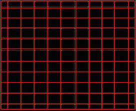 |
fig 3 |
Then we can use the Mask-Image feature to paste the CCD image on design, please note that the figure in the CCD points is the darkest black cloth, but the density is the highest after import, so please set the reverse colors as TRUE as shown in Figure 4.
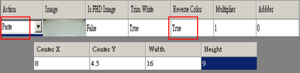 |
fig 4 |
The current design is shown in Figure 5.
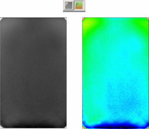 |
fig5 |
Extract density
We can use the extract density function to converse density. After pressing the extract density button function as shown in Figure 6,
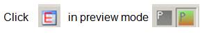 |
fig 6 |
Screen pop up a window allowing you to select the pre-saved layer file like Figure 3, and then the screen will be retrieved out of a new form, the form containing the Run2Run table and density table shown in Figure 7.
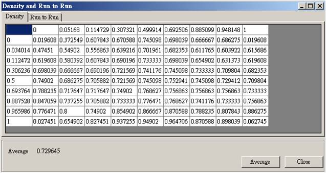 |
fig7 |
Density transfer values can be seen as the brightness relationship. In density form, you can edit the density to avoid the distortion problems caused by CCD image issue as shown in Figure 2, the four corners of the dark band . Editing functions are similar to general spreadsheet as shown in Figure 8. Press average buttom can calculate the average density (brightness)
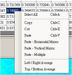 |
fig 8 |
Luminance conversion
To compare the conversion value and actual measured values, we can fit a liner relationship.Finally we get slope and intercept values in Figure 9.
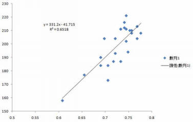 |
fig 9 |
We can type it into the parameters A (slope), B (intercept value) of Run2Run table.Finally, type all information (see Equation 4), if checked "add 1 to result" the results is Equation 5, if not Check the results is Equation 6.
1+Factor*((Target-L0)/L0)-----(5)
Factor*((Target-L0)/L0)-----(6)
We used Equation 5 in this example. Press calculate buttom the final result of Equation 5 can be obtained, select and copy the results shown in Figure 10.
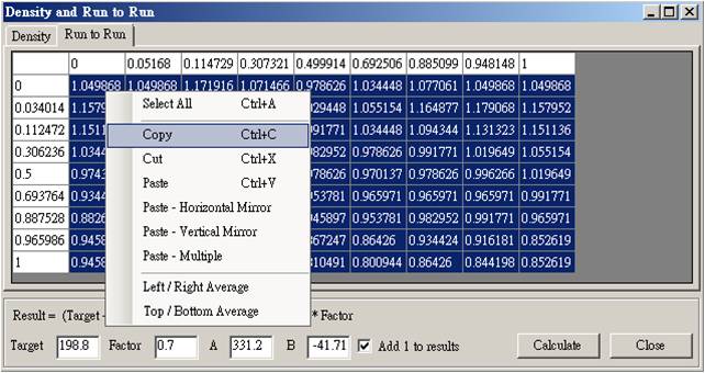 |
fig 10 |
Amend the original design
You can save original design as a new version design to distinguish the design and calculation the new values. In the new version designed open the editor density, density of the form click the upper left corner, and then select Paste-multiple right-Figure 11
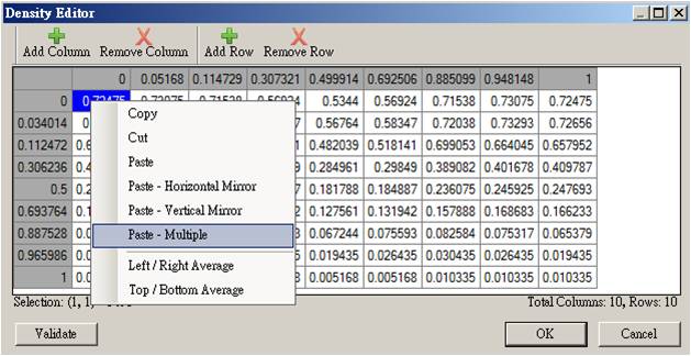 |
fig 11 |
Its role as Equation 4. If require you can make symmetric in Figure 12
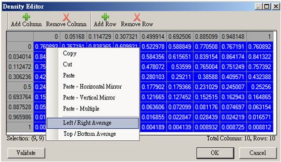 |
fig 12 |
Final confirmation
At this point you have completed the new design, and finally use density profile editor to ensure that the smoothness of each line of a design shown in Figure 13. Congratulations you have completed the work.
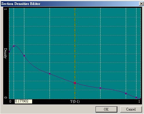 |
圖13 |
Fixed the hot spot caused by LED and institutions
The above method has been to achieve uniformity of customer requirements, but some, such as the hot spot caused by LED and institutions to use the grid to deal with, is inviting trouble, we provide mask-block/image to solve, we leave the next one article and instructions.
Looking for backlight design tool? BacklightFly is the best one!