index(polar coordinator)
Backlight Design of Polar coordinate system
email: support@febees.com
Abstract
After reading the three previous articles, for a general light guide design should be easily controlled, but for some irregular curvature of light guide plate, such as table lamps and special hot spot eliminate parts is still very difficult.
Preface
General light guide shape of TV and notebook are rectangular. So very direct way with the mesh and easy to use, but for the hot spot fixed parts and table lamps, because much more varied, so we try to use the polar coordinate approach to the design. We will be the following two examples to illustrate:
- An hot spot fixed parts with X, Y direction of the circular patches of different density components.
- Design of an actual desk lamp.
Concept
We tried to use the polar coordinate approach to the design, we can define the origin of coordinate in the design of any one position, from origin to any edge boundary distance normalized to 1, so our R is from 0 to 1, assuming that the origin in the middle, we can range of design inscribed circle as shown in Figure 1.
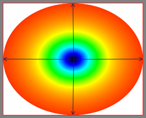 |
Fig 1 |
Therefore, the proposed design is sqrt (2) ~ 1.414 multiple than the actual length and width to form circumcircle, and design within the range in the blue box, the design would be more convenient as shown in Figure 2.
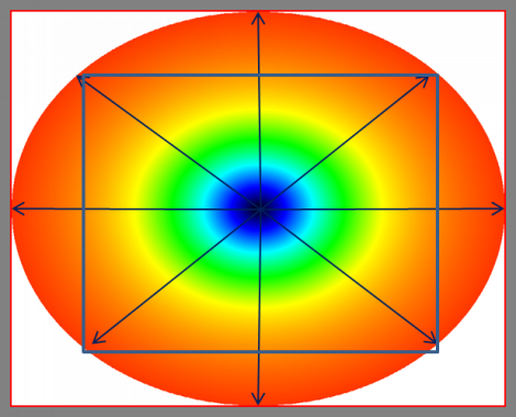 |
Fig 2 |
Then if the center is not the center of the design draft,the distance from the center to the edges is still 1, the center to the corner of the inner rectangle is exactly 1. The design line which marked as a blue arrow is from 0 to 1 to indicate in Figure 3.
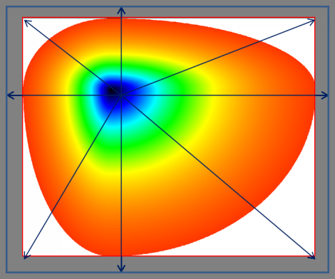 |
Fig 3 |
Definition
We must abide by the following principles can be used to design the polar Refer to Figure 4.
- Design Line: from the center of the circle to one direction of strength line, the total length is 1, the actual length of the instructions refer to Figure 1,2.
- Angle Theta: The angle between the horizontal line and design line , the definition is 0 ~ 360.
- Location: We can set some control points on design lines, the distance between origin and control point is location, the first location must be 0 and the last one must be 1, the middle position can have a variable number of control points but we call the locations must be small to large, the distance need not the same.
- Density: each control point must have a density value, the origin density of each design line should be the same, because physically the same position (center), of course the same density.
- Tthe number of design lines must be 1 or 3 above, shall not be 2.
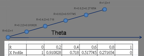 |
Fig 4 |
Case 1:
Suppose we want to paste in the bottom of the design draft of a X, Y circle of different density as Figure 5 to fix the problem of hot spot, how to design? As to how the combination of the original design are no longer issued instructions please refer to previous articles.
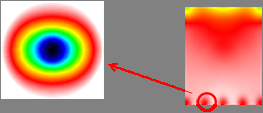 |
Fig 5 |
First, we use the inscribed circle in Figure 1 is designed with four control lines which theta were 0,90,180,270, where X direction theta 0 the same design with of theta 180, Y direction theta 90 the same design with of theta 270 as shown in Figure 6.
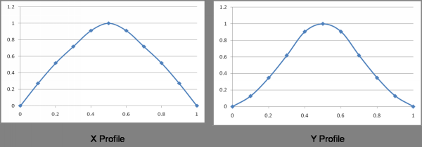 |
Fig 6 |
The system will automatically produce the draft design shown in Figure 7.
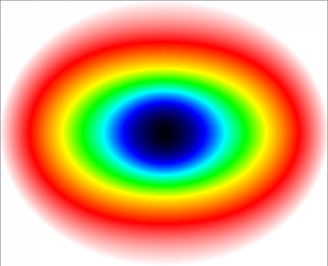 |
Fig 7 |
Then using the same mask-block function can achieve the elimination of hot spot as shown in Figure 8, please refer to the "Backlight Design of HotSpot elimination ABC".
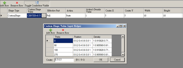 |
Fig 8 |
Case 2:
A table lamp design with LED in the center shown in Figure 9.
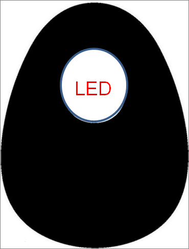 |
Fig 9 |
The design shown in Figure 2, we use the circumcircle way, the design is than the actual 1.414 times (sqrt (2)), thus ensuring the distance of center to any corner of the rectangle inside is 1. There are 8 design line which theta were 0,45,90,135,180,225,270,315 degrees, and the center is not in the center of design, its location in the (0.5,0.3476) in Figure 10.
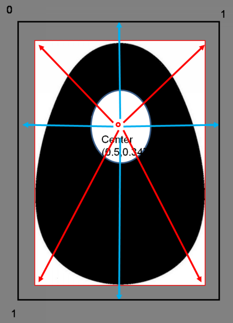 |
Fig 10 |
Because of the design line through the emplty area, the density would have zero which were caues curve unsmooth shown in Figure 11.
 |
Fig 11 |
Recommended to set this density profile in the general mesh editor, to adjust the empty density to get smooth curves, and finally the empty area will then filter out other ways as shown in Figure 12.
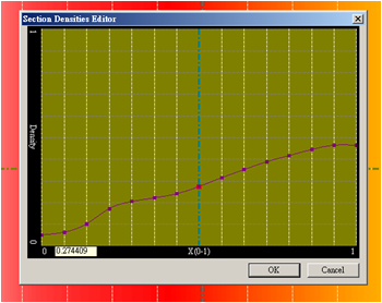 |
Fig 12 |
All the density line data entry system will be a preliminary design is shown in Figure 13.
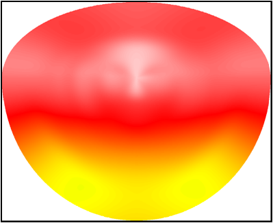 |
Fig 13 |
We then use Mask-block in the mask in mask feature to filter out the shape of the desk lamp as shown in Figure 14, the results obtained.
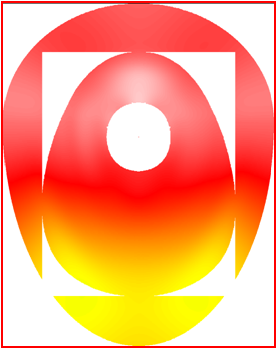 |
fig 14 |
Finally, use Mask-include/exclude to include center design, thus completing the product design as shown in Figure 15.
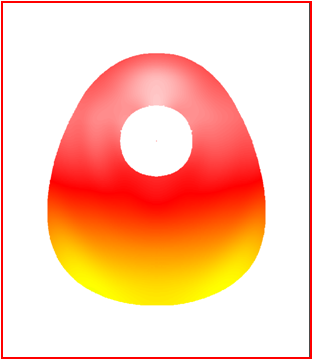 |
Fig 15 |
Final confirmation
At this point you have completed the new design,using measurement and analysis tool in the preview mode as shown in Figure 16.
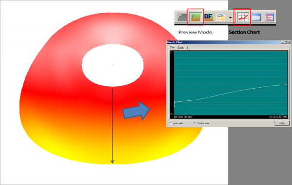 |
Fig 16 |
Revised draft again
You can simply change the location and density of control points can easily modify the design draft. I believe in the near future polar mesh design and the Mask will be like a new operating standards.
Looking for backlight design tool? BacklightFly is the best one!