index(hot spot ABC)
Backlight Design of HotSpot elimination ABC
email: support@febees.com
Abstract
According to the previous article to design light guide plate, in principle, should be able to get a uniform brightness of the design, in recent years widespread use of the LED light source, such as the non-uniform brightness of light sources has become a new cause trouble, this article describes how to use BacklightFly to resolve.
Preface
When the light from the CCFL line source into a LED point light source, the entry of light into the light guide must be designed to overcome the problem of uneven distribution of light intensity, which is the so-called Hot Spot, can generally be handled from the following:
- Use of cover part of the shelter into the light side, this approach is the most straightforward, but will cause a waste of space and light intensity loss, for high-end product is not mainstream.
- Use mechanism such as concave or convex lens to punch through the point source scattered manner, this approach is currently used more in small devices such as keypad LED light source and sppeical product.
- Change the density distribution to improve, this approach is used in the NB and the TV main way, of course, would be more effective with 1,2 together.
This article only focuse on case 3
Concept
Use of the grid to do backlight design is the mainstream after our promotion, customers try to fix the LED hot spot with the grid method, found that to use the grid to handle must do the following:
- Grids must align LED design and location.
- Have more grid in dramatic density change area to handle.
- Spline curve calculated according to the grid often have unexpected results occur, although use different spline method can solve this problem, but in the end was not friendly for designers.
The example is shown in Figure 1, X direction of the design up to 129 lines, greatly increating the difficulty of the design
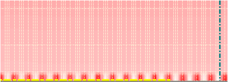 |
Fig 1 |
BacklightFly V3 introduce the new design concepts Mask Block. This concept significantly reduce the design complexity, has become the object of emulation, as the grid is also a common industry-standard practices
Separate the hot spot of the LED then do the density of point to point processing, use the default smooth components combined with the original draft design to achieve the following objectives:
- Do not change the original design of the grid lines (designed to maintain a small number of lines)
- Component can be adjusted according to hot spot shape size and correction amount
- After the processing keeps smooth and continuous, to ensure good taste.
Components
Three goals mentioned earlier, the third is the most basic and important. To achieve this goal must have the following conditions:
- Density change must be smooth
- The combination of components and original surface must naturally
First, we used the default component with Boltzmann distribution, to ensure the density smoothness after combined with the original as shown in Figure 2
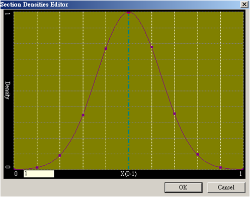 |
Fig 2 |
Then we verify whether this approach can solve the problems we encountered the following:
- Size change of Hot Spot
- Modify amonut of Hot Spot
- Shape of Hot Spot
- Modify curve of Hot Spot
To meet the requirements of our counterparts in the following way:
- Components using grid design approach, so changes will not affect the element size and smoothing effect.
- Formalize the components, component design values from 1 to 0, and then combined with the original operation witn any correction.
- Most of Hot Spot can use oval shape to handle, but there may be caused by overlapping or non-LED Hot Spot ,such as mechamic hot spot, the reader can edit the grid like normal design to create a new component, we remain in the future article.
- Correction curve is common issue, experiments show that using simple Boltzmann distribution can achieve the desired results, if need, readers can create their own components, we will also be introduced in a future article .
Combined with the original design
Apart from new components need to establish their own components , how can we use the default components to correct our hot spot. First customers will be asked to measure the brightness curve of Hot Spot, and the length and width of the range shown in Figure 3.
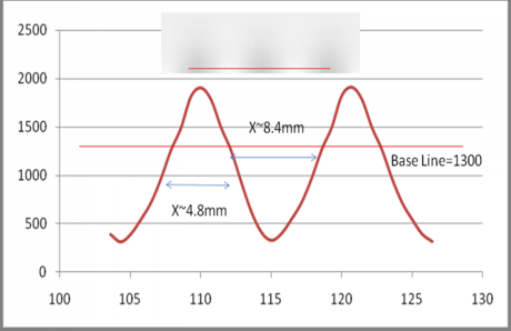 |
Fig 3 |
Next we decided to use synthetic operation modes:
- Add mode:Add components value into original design (component+original design)
- Add percentage mode: Original design*(1+component)
- Paste mode:replace original design with component
Generally recommended 1 or 2, we use Mode 2 to explain the procedure
We have the information shown in Figure 3:
The center luminance profile of Hot spot
L=f(x) , f(y)—(1)
Size of Hot spot:
X,Y—(2)
First, all divided by the brightness of the background brightness data about 1300, the percentage can be distributed as formula (3)
Lperctage=L/base_line —(3)
Result of the operation ranged between 140% to 20% as shown in Figure 4.
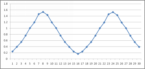 |
Fig 4 |
Inverse relationship between density and brightness, that is to be amended to the original density of 0.714 ~ 5 times (1/1.4 ~ 1/0.2) as formula (4).
Dperctage=1/ Lperctage —(4)
Converted to add percentage is -0.286 ~ 4 (0.714-1~5-1), so we get 4 times increase in dark areas, and minus 28.6% in bright areas as formula (5).
Dadd_perctage= Dperctage-1 —(5)
According to experience , X,Y of component is 1.667 times of measured values(Boltzmann distribution of the actual distribution of the conversion experience) as formulas(6),(7)
Xset=X/0.6=X*1.667---(6)
Yset=Y/0.6=Y*1.667---(7)
Then we can implement one component to the front of the LED (light area) with a value =- 0.286 and x, y size equal to 8,14, between the LEDs stick a value = 4 x, y size equal to 14,14, Through the help of a spreadsheet, we quickly copy and paste the full 65 components (32 LED) as shown in Figure 5.
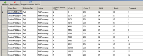 |
Fig 5 |
Complete the design shown in Figure 6.
 |
Fig 6 |
New method X direction keep same grids of 11 design lines , Old method need about 129 lines as Figure 1,The new is simple and beautiful.
Final confirmation
At this point you have completed the new design,using measurement and analysis of final profile in the preview mode as shown in Figure 7
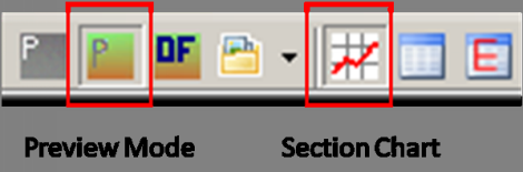 |
Fig 7 |
To ensure the results as expected as shown in Figure 8.
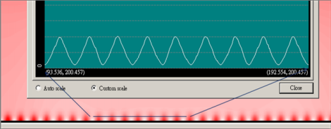 |
Fig 8 |
Congratulations you have completed this draft.
Revised draft again
Hot spot modify in principle not affect the overall optical behavior, so the modify is issued once again you can choose to make changes to the original components directly or Hot Spot image processing to original design we will examplein the future article.
Looking for backlight design tool? BacklightFly is the best one!